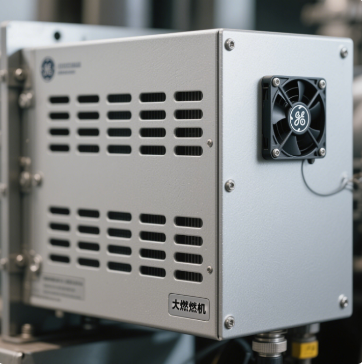
GE gas engine control system has developed from MARK I, MARK II, MARK III, MARK IV to MARK V, MARK VI and other series. The following is a specific introduction to each series:
MARK I1
Birth time: It started in 1968.
Technical features: It adopts a solid-state series component analog control system, relay sequence control and output logic, and on average, each control panel has 50 printed circuit boards, providing three input circuits: start-up, temperature and speed. The work follows the principle of "association redundancy", that is, if a control parameter (such as temperature) fails, the speed control is used as a backup.
MARK II
Birth time: Started in 1973 2.
Technical features: The solid-state logic system is adopted to improve the compensation, removal, calculation, etc. of the temperature measurement system, and an integrated temperature system is added, which strengthens the control ability of exhaust temperature and can automatically remove damaged exhaust thermocouples 12.
MARK III1
Birth time: Started in 1976 2.
Technical features: The use of integrated circuits is GE's first gas engine control system using microprocessors and the first system to provide triple modular control, but it is only used in small and medium-sized steam turbine systems, and only has a small number of applications in the electro-hydraulic market, and is less used in the gas turbine control field.
MARK IV
Birth time: Started in 1982 2.
Technical features: For the first time, triple modular redundant control is provided for gas turbines and steam turbines, and redundant microprocessor control is adopted, and the circuit is integrated in large quantities. Updated operation and display methods, relying on CRT, auxiliary display and operation software to control, simplifying panel layout. Communication uses RS-232 or RS-485 to transmit 12.
MARK V
Birth time: put into use in 19912.
Technical Features: Can be set as triple modular redundancy (TMR) or a single Speedtronic turbine control system. The fault tolerance system has been improved, and the hardware method of MARK IV has been switched to software fault tolerance (SIFT), which improves operational reliability and facilitates online maintenance. The color graphic display and the human-computer interface of the standard keyboard have been used to improve the protection system of the control cabinet and improve safety12.
MARK VI
Birth time: Started in 19992.
Technical features: The Ethernet TCP/IP protocol is used to achieve internal and external communication, and the concept of an integrated control system (ICS system) is introduced, integrating gas turbine control, steam turbine control, generator excitation and protection control, waste heat boiler control and auxiliary system control in the power station. The control module continues to use the R/S/T three-module redundant TMR control technology. Each I/O card has a TMS320C32DSP processor to improve computing power. The data stream uses 32-bit floating point data2.
The content of the GE gas turbine control system instruction manual is usually quite complex. Here, taking the common Mark VI series as an example, it is introduced to you from aspects such as system overview, hardware configuration, and software functions:
System Overview
- Control Functions: The Mark VI control system has a variety of control functions, including start-up control, speed control, temperature control, fuel control, etc., to ensure the stable operation and high-efficiency performance of the gas turbine. For example, the start-up control function is responsible for managing the start-up process of the gas turbine from the cold state to the hot state, controlling the action sequence and time nodes of equipment such as the starting motor and fuel valves to ensure the safe start-up of the unit.
- Protection Functions: It has a complete protection system, which can provide all-round protection for the gas turbine, such as overspeed protection, over-temperature protection, flameout protection, vibration protection, etc. When it detects that the operating parameters of the unit exceed the safe range or abnormal situations occur, the protection system will act quickly, triggering emergency shutdown or other protection measures to prevent equipment damage and accidents.
Hardware Configuration
- Controllers: High-performance controller modules such as IS420UCSBH4A are adopted, with a robust and durable industrial-grade design that can operate stably in harsh environments. These controllers have a variety of input and output channels, which can be connected to various sensors and actuators to achieve the monitoring and control of various parameters of the gas turbine.
- Input and Output Modules: These include analog input and output modules, digital input and output modules, etc. The analog input modules are used to collect analog signals such as temperature, pressure, and flow rate, while the digital input and output modules are used to control on-off devices, such as the opening and closing of valves and the starting and stopping of motors.
- Communication Modules: Equipped with interfaces such as Ethernet and serial communication, it can communicate with other devices or systems to achieve data transmission and remote monitoring. Through the communication network, operators can conduct real-time monitoring and operation of the gas turbine at the remote control center, which improves the flexibility and manageability of the system.
Software Functions
- Operation Interface: It provides an intuitive and user-friendly operation interface. Operators can view the operating status and parameter information of the gas turbine in real-time through the interface and perform various operations and settings, such as starting up, shutting down, and adjusting parameters. The interface usually displays the main operating parameters of the unit, such as speed, temperature, pressure, power, etc., as well as the operating status indicator lights of the equipment, which facilitates operators to quickly understand the operating situation of the unit.
- Control Programs: Based on Programmable Logic Controller (PLC) technology, it is programmed using programming languages such as Function Block Diagram (FBD) and Ladder Diagram (LD). According to the operating logic and control strategy of the gas turbine, the control program processes and analyzes the collected signals and outputs control signals to the actuators to achieve precise control of the unit.
- Data Recording and Analysis: It has the functions of data recording and analysis, which can record various data during the operation of the gas turbine in real-time, including operating parameters, alarm information, operation records, etc. These data can be used for fault diagnosis, performance analysis, maintenance management, etc., helping operators to promptly discover potential problems of the unit and optimize the operating performance of the unit.
Installation and Maintenance
- Installation Requirements: When installing the GE gas turbine control system, strict installation specifications and requirements need to be followed. This includes that the installation positions of devices such as controllers and input and output modules should meet the design requirements to ensure good ventilation and normal heat dissipation; the laying of cables should avoid interference to ensure the stability and reliability of signal transmission; the grounding system should comply with relevant standards to ensure the safe operation of the system.
- Maintenance: Regular maintenance of the control system is the key to ensuring its normal operation. The maintenance content includes checking the operating status of the equipment, cleaning the dust on the surface of the equipment, tightening the connecting parts, and checking whether the cables are damaged. At the same time, it is also necessary to regularly upgrade and back up the software of the system to ensure that the system has the latest functions and security.


 Bentley 3500 series module sup
 ABB module supplier Guizhou Yu
 ABB supplier
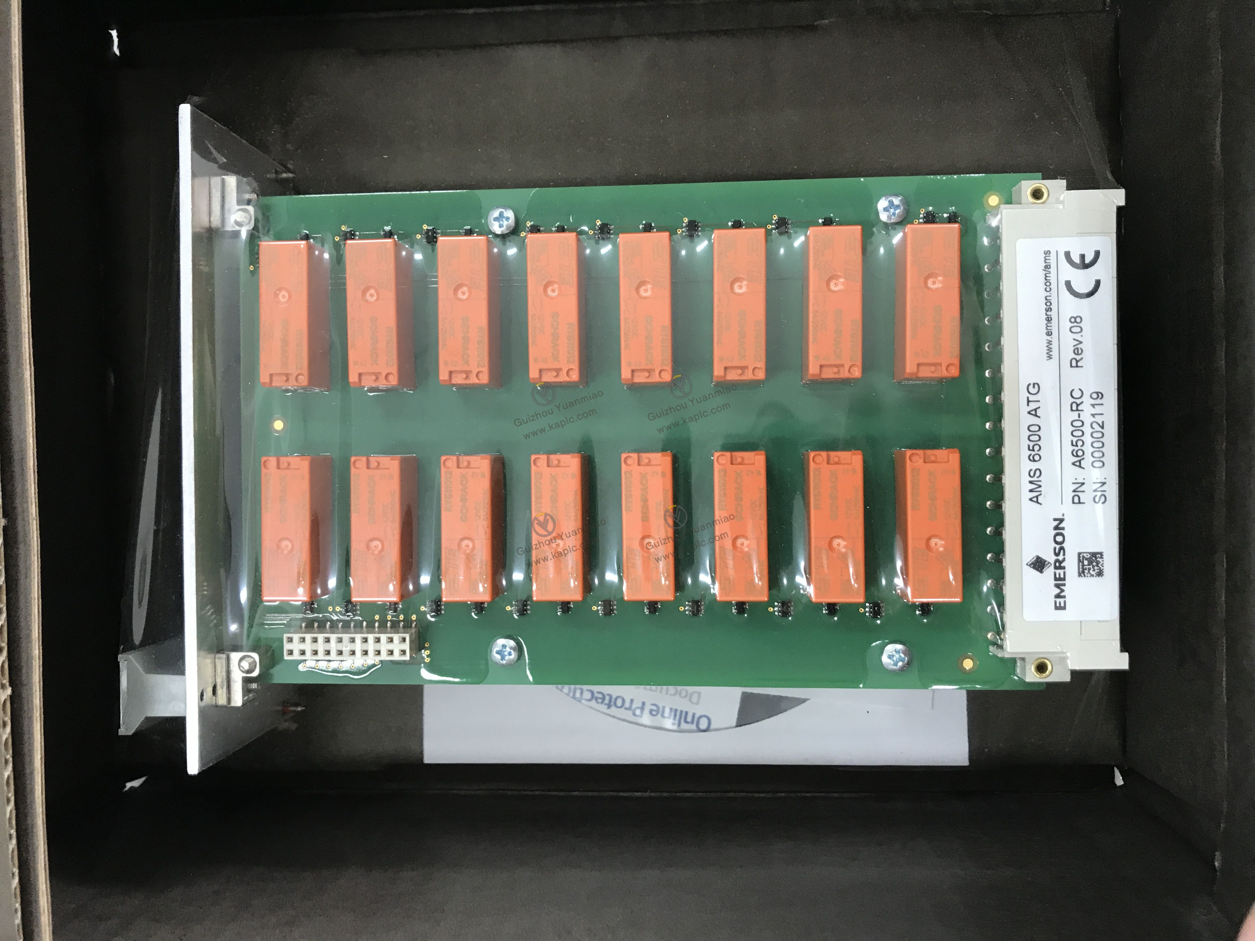 A6500-RC